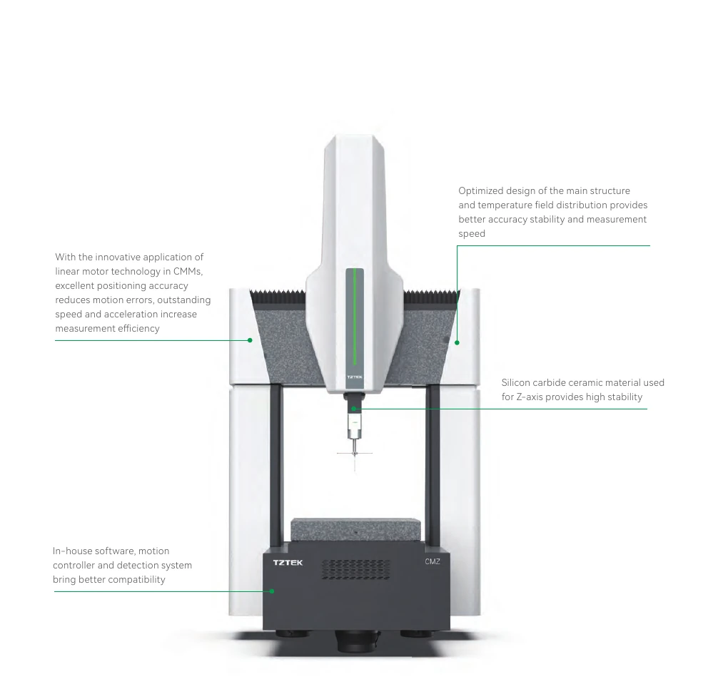
 CMZ
CMZCMM / CMZ
CMZ Zenith Series
CMZ 06.08.06 · CMZ 08.10.06 · CMZ 10.12.08 · CMZ 10.15.08 · CMZ 12.15.10 · CMZ 12.20.10
- Range
- 600 × 800 × 600 to 1200 × 2000 × 1000 mm
- Length measurement error
- MPE(E0) from (0.5+L/500) µm

PKL / PRECISION MEASUREMENT
PKL helps manufacturers select the right CMM system for GD&T, machined parts, automotive components, mold, jig, fixture, and precision 3D measurement requirements.
Actual manufacturer catalogue images are paired with the public selection specifications below. Use the model list to narrow the discussion; PKL confirms the final configuration.
CMZCMM / CMZ
CMZ 06.08.06 · CMZ 08.10.06 · CMZ 10.12.08 · CMZ 10.15.08 · CMZ 12.15.10 · CMZ 12.20.10
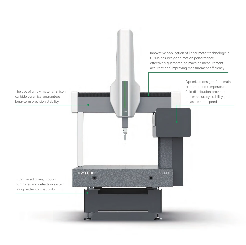 CMU
CMUCMM / CMU
CMU 06.08.06 · CMU 08.10.06 · CMU 10.12.08 · CMU 10.15.08 · CMU 10.20.08 · CMU 12.15.10 · CMU 12.20.10 · CMU 15.20.12 · CMU 15.25.12 · CMU 15.30.12
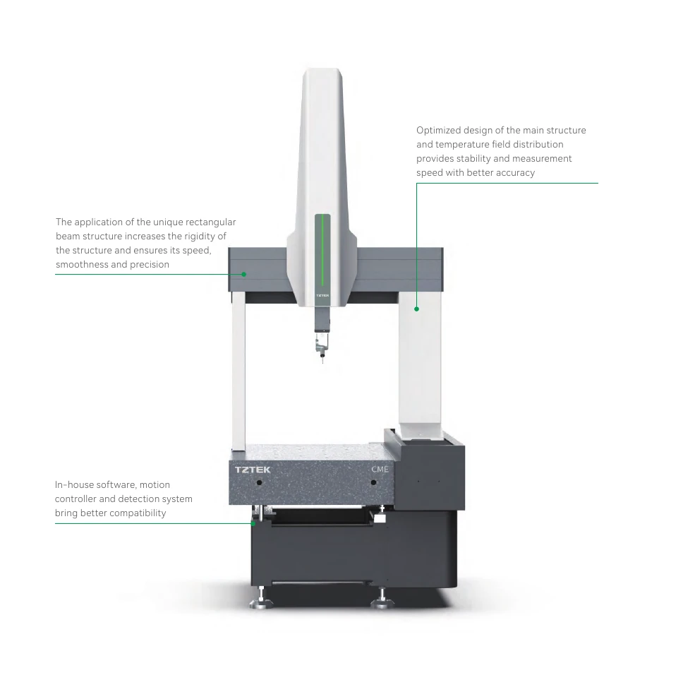 CME
CMECMM / CME
CME 06.08.06 · CME 08.10.06 · CME 10.12.08 · CME 10.15.08 · CME 10.20.08 · CME 12.15.10 · CME 12.22.10
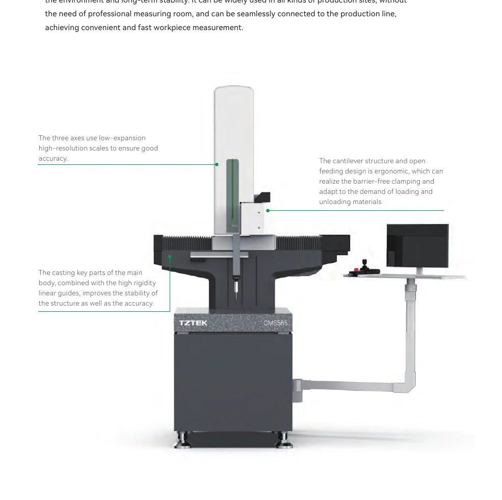 CMS
CMSCMM / CMS
CMS 05.06.05
A Coordinate Measuring Machine is used for accurate 3D dimensional inspection. Depending on configuration, it measures parts using contact probing and can support scanning workflows for complex shapes, machined features, and quality control requirements.
Measure X, Y, Z geometry and dimensional relationships that need more than simple visual checks.
Select tactile probing, scanning, and fixture approach based on the part, tolerance, and inspection workflow.
Use CMM data to support dimensional reports, GD&T checks, production validation, and inspection planning.
Use CMM when your inspection problem depends on true 3D geometry, tight tolerances, tactile probing, or complex features that need reliable dimensional evidence.
Validate milled, turned, ground, and precision-cut parts where dimensions depend on 3D relationships.
Support dimensional control for housings, brackets, shafts, gears, assemblies, and production-critical parts.
Check hard tooling, fixture datum, mold surfaces, and setup references where geometry must stay controlled.
Use CMM for position, flatness, profile, perpendicularity, true position, datum structures, and complex features.
Larger precision parts where CMM travel, load capacity, and inspection environment are suitable.
Inspect bores, datums, internal features, planes, and touch-measured points where optical-only inspection is not enough.
PKL does not over-specify from a catalog. We confirm the model recommendation based on part size, tolerance, material, environment, and inspection workflow.
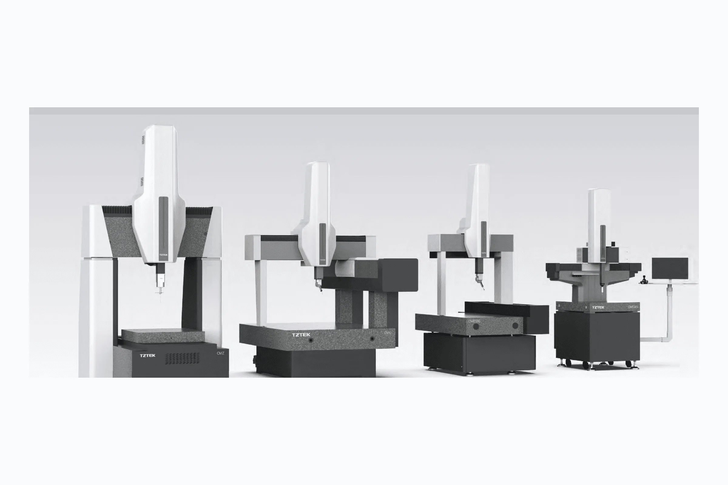
A practical CMM family for teams that need stable dimensional inspection in QC and production environments.
Recommended when tolerance, part stability, measurement strategy, and reporting requirements demand tighter control.
Probe configuration is selected around access, feature type, cycle time, data needs, and operator workflow.
See real CMM application visuals for production parts, tactile probing, complex geometry, and customer-specific evaluation scenarios.
Dimensional inspection for milled, turned, ground, and precision-machined features.
Check brackets, housings, shafts, gears, and production components with 3D inspection needs.
Validate tooling surfaces, fixture datum, setup references, and critical hard-tool geometry.
Evaluate profile, position, flatness, datum structure, and compound reference geometry with tactile 3D measurement.
Review part size, weight, access, load capacity, and fixture strategy before choosing the right CMM approach.
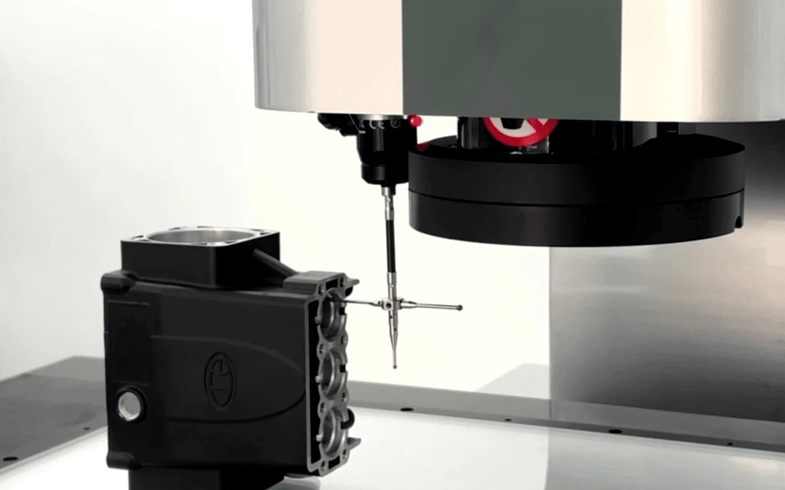
Not sure which measurement system is right? PKL helps define the path from your actual part, tolerance, inspection method, and production workflow.
Your inspection depends on 3D geometry, GD&T, contact probing, machined parts, mold, jig, fixture, complex surfaces, or deeper feature control.
You need fast optical inspection for small, flat, thin, visual-feature parts such as rubber, plastic, PCB, glass, and batch measurement work.
Let PKL Recommend the Right SolutionFrom part evaluation to installation, training, service, rental, trade-in, and automation integration, PKL supports the full decision and ownership path.
Tell us about your part, material, tolerance, current inspection method, and production environment. PKL will recommend the CMM path that fits your real application.
For faster consultation, include part type, material, approximate size, tolerance requirement, current inspection method, and any available drawing or sample photo link.
THE NEXT PRACTICAL STEP
Share the geometry, tolerance and inspection goal for an application-led recommendation.